Lohit Balakumar
Vanderbilt Robotics Team
As a member of the frame and drive team I help design and prototype parts on the drive system for the Lunabotics competition.
Motor Plate
We looked to make a few improvements to the motor plate from the year before. First, the previous motor plate only had one mounting point. This caused a lot of stress on the joint resulting in warping of the plate. Second, the tensioning for the pulley system would adjust by rotating the motor across the slot, and securing it with a bolt as a friction fit. This was not good as it kept loosening as the robot drove around, reducing tension in the pulley. To solve the first issue, we added a second mounting point and a beefier piece of aluminum (1/4" thick), which prevented the warping. For the tensioning system, we initially considered switching to a chain and sprocket system to prevent any slipping however due to the terrain, we determined that we did want some slipping with a pulley system to prevent motor overload. It also wasn't the appropriate testing system due to the risk of sand or dirt clogging the chain. We implemented a dynamic tensioning system by slotting 2 bearings outside the pulley, moving the bearings across the slot, until the pulley was tensioned, and bolting it down.

Previous Motor Plate in Assembly

New Motor Plate in Assembly
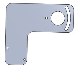
Previous Motor Plate

New Motor Plate
LIDAR Gimbal
We needed a gimbal for the LIDAR to stabilize it for steady data acquisition. I decided to use a similar design as the motorized gimbal I had also worked on. I designed an enclosure to secure the LIDAR. It had an angle range of 270 degrees so I tried not to cover any of the lens when securing it. The intention was to control it with a closed feedback loop with an Arduino. We decided not to go with this design due to its lack of robustness and inability to utilize the main power supply on the robot.

Front View of Gimbal
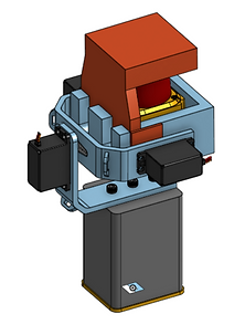
Back View of Gimbal
Skills
Machining || OnShape || 3D Printing || Prototyping || Mechanical Design
Results/Lessons Learned
-
Motor pulleys remained tensioned much longer and motor plate did not warp
-
Iterate as much as possible. I tried reverse engineering the mesh model of the gimbal setup in CAD as apposed to 3D printing it and measuring it by hand to avoid wasting filament. Ultimately, it would have been easier and less time consuming to just 3D print it and use calipers
-
I learned a lot about static and dynamic tensioning systems, what their applications are, and when to use them